Bookmarks from a mesh — eight parts, one kerf, two sheets
A 15.9 MB Halloween STL arrived as a flat 1 mm relief, drawn at an angle, with seven bookmark silhouettes and a tag buried in it. This is the run that turned it into cut-ready DXF: section at mid-thickness instead of projection, Ø4 tassel holes placed where the filigree actually has material, 0.075 mm kerf compensation on every contour, and a shelf nest proven to fit — 0 overlaps, 3.21 mm minimum gap, 0 DXF audit errors.
Kerf is not a margin you add at the end — it is the difference between a part that measures 200.0 mm and one that measures 199.85. Every outer contour in these files is offset 0.075 mm inward and every hole 0.075 mm outward, so the beam's own width does the rest and the plywood comes off the bed at nominal size.
What came in
The STL is not a solid you can slice into separate models — it is one flat extrusion, 1 mm thick, with all eight silhouettes on the same plane and the whole drawing rotated. That shape dictates the method: a planar section at z = 0.5 mm returns closed 2D loops for every body, where a projection would return a pile of overlapping edges. Each loop is then squared up to its minimum rotated rectangle, which is what un-rotates the artwork without resampling it.
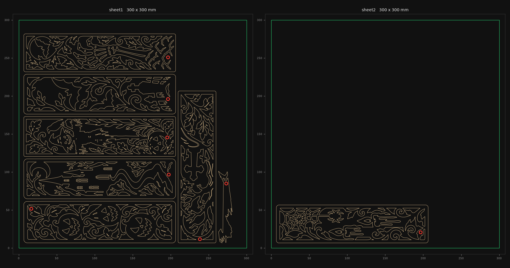
CUT, red = TASSEL, green = the REF-300x300-DO-NOT-CUT bed outline. Sheet 1 holds six bookmarks plus the tag; sheet 2 holds the seventh.The pipeline
1 · Section, don't project
Slice the mesh at mid-thickness. The result is watertight by construction — 0 boundary edges — because the source is a closed extrusion. Interiors that survive the slice are real holes, not tessellation seams.
2 · Filter at the kerf, not at zero
Any hole narrower than about twice the kerf can't be cut: the beam closes it into char. Width is measured with GEOS' inscribed-circle call rather than a bisection loop — the same answer, orders of magnitude faster. 31 holes between 0.08 and 0.27 mm were dropped; 334 were kept.
3 · Place the tassel hole by clearance
Each bookmark is rasterised at 0.2 mm and run through a distance transform, which gives the distance from every point to the nearest cut edge. The hole goes where that field is deepest, preferring 10 mm in from an end and centred across the width. The mask is padded with void first — without that ring the field thinks the panel edge is infinite material and drops holes 2 mm from the tip.
4 · Compensate, then nest
Kerf offset applied to every loop, then shelf packing with 6 mm margins and 3 mm gaps. The nest is checked after the fact, not assumed: pairwise intersection area, pairwise distance, and every bounding box against the bed.
The parts
Nominal finished sizes. Hole position is measured from the part's own bottom-left corner, in mm.
| # | Sheet | Size | Cutouts kept | Dropped | Tassel hole at | Wall → outer edge | Min wall, any cut |
|---|---|---|---|---|---|---|---|
| 1 | 1 | 200.0 × 55.0 | 48 | 0 | 10.0, 45.0 | 7.81 | 1.27 |
| 2 | 1 | 200.0 × 52.5 | 45 | 0 | 191.0, 31.8 | 7.06 | 1.46 |
| 3 | 1 | 200.0 × 52.5 | 77 | 28 | 189.0, 25.0 | 9.03 | 1.41 |
| 4 | 1 | 200.0 × 50.0 | 49 | 0 | 190.0, 19.0 | 8.04 | 2.80 |
| 5 | 1 | 200.0 × 50.0 | 39 | 1 | 5.0, 21.2 | 7.81 | 1.30 |
| 6 | 1 | 200.0 × 52.5 | 21 | 2 | 190.0, 19.8 | 7.06 | 1.64 |
| 7 | 2 | 200.0 × 50.0 | 55 | 0 | 190.0, 14.0 | 8.05 | 1.53 |
| 8 · tag | 1 | 94.7 × 18.3 | 0 | 0 | 78.2, 8.0 | 1.36 | — |
The tassel hole is cut at Ø3.85 mm, not Ø4.00: the kerf widens it by the beam width on the way round, so the finished hole measures 4.00 mm. Holes sit 7–9 mm in from an end on the seven bookmarks — the tag is the outlier at 1.36 mm of material, which is the one place in the set where a ribbon could tear out.
Why two sheets, not one
Seven 200 mm bookmarks plus a tag cannot share a 300 × 300 bed. The arithmetic is unforgiving: usable area after margins is 288 × 288 mm, and seven 200 × 52 pieces need 73,500 mm² of stock — 89 % of it — with rectangles 3.8:1 that must sit axis-aligned. The best shelf arrangement reaches six, so the seventh gets its own file rather than a forced overlap. Sheet 1 lands at 44 % net material because the filigree is mostly hole; the leftover stock is what the seventh is cut from if you'd rather not load a second sheet.
Cutting it
| Layer | Contents | In LightBurn |
|---|---|---|
CUT | Every through-cut — outers and filigree | 100 % power, 300 mm/min, 1 pass on 3 mm ply |
TASSEL | The 8 tassel holes | Same settings, priority above CUT so holes cut first and the part stays rigid |
REF-300x300-DO-NOT-CUT | Bed outline + label | Output off — reference only |
300 mm/min is the machine's own tested number for 3 mm ply on this diode, not the community figure — real output varies 2–3× between units of the same "20W" rating. Start on sheet 2 (one bookmark) as a test coupon: if the 0.4 mm ligaments char shut or the frame warps, drop to 250 before running sheet 1. Air assist on, focus on the ply surface, absolute coordinates, and no extra kerf offset in the cut settings — it is already in the geometry, and adding it again would pull the holes down to about 3.7 mm.
Honest limits
- Position, not centring. Holes sit where the filigree leaves a solid pocket near an end. On two parts that is a few millimetres off the centre line — worst case 11 mm of a 50 mm width. A solid 10 mm header band would fix it and cost 10 mm of artwork per bookmark.
- 1.27 mm is the weakest wall. That is plenty for a ribbon in shear through 3 mm ply, but this is a decorative bookmark, not a load-bearing hole.
- The tag's 1.36 mm to the outer edge is the single fragile spot in the set.
- Source thickness is 1 mm. The DXF is 2D and thickness-agnostic; the 3 mm figure is your stock, and it is what the power/speed advice assumes.
- Not tested on the bed. The geometry is verified numerically — overlaps, gaps, closure, units — but nothing here proves how this particular ply chars. That is what the test coupon is for.
Files
- bookmarks-sheet1.dxf — 6 bookmarks + tag, 331 polylines
- bookmarks-sheet2.dxf — 1 bookmark, 59 polylines
- stl-to-dxf-pipeline.py — the converter, if a shape needs re-cutting at a different size
Verified 2 Nov 2026 — 0 overlaps · 3.21 mm min gap · 0 audit errors · all parts inside 300 × 300